The Bean Can Battery

A 1.2v Iron-Iron Alkaline Cell From Scrounge

This is not a science project. It’s a real, rechargeable, deep-cycle cell you can build from trash. It’s based on the old Edison nickel-iron battery, but simplified to use only iron and rust. No lead, no lithium, no acid.

Nominal voltage is 1.0-1.2V per cell. Put 5 in series for ∼6V, 10 for ∼12V.

Base Concept

1. Anode (-): Clean iron. A plain steel can packed with plain steel wool that’s been heated once in a can to burn off oil – no coating. When discharging, the iron turns to iron hydroxide (rust) and releases electrons.
2. Cathode (+): Rusted iron. Steel wool that you let rust, then packed tight.
3. Electrolyte: Alkaline water that carries ions between them. The electrolyte does not get consumed.

You are just shuttling oxygen between two pieces of steel in different oxidation states.
1. The Anode – The Outer Can

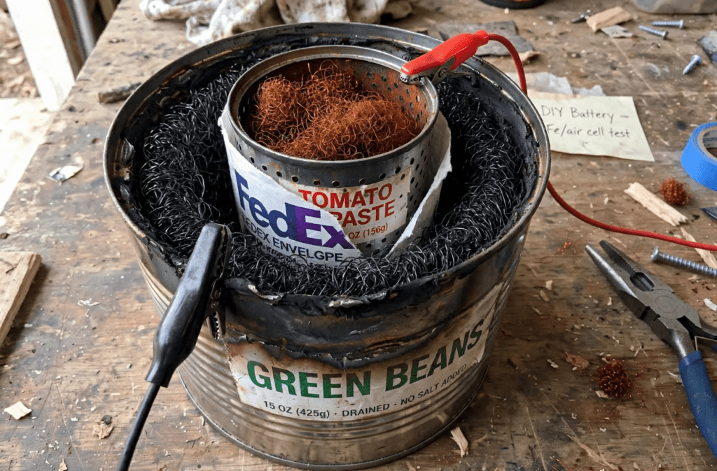
Best option is a standard 15oz steel vegetable can. This is your negative terminal. The can itself IS the battery case and the anode.

Most food cans today have a thin plastic liner inside to prevent corrosion. You must remove it. Easiest scrounge method: hit the inside with a propane torch or throw it in a campfire for 2-3 minutes until the liner smokes and burns off. Dont breathe the fumes! Then quench in water and hit it quickly with sandpaper or steel wool to expose bare shiny steel. An unlined can is what you want.

Options: any steel can, steel box, steel pipe, or even an old ammo can. Avoid aluminum.

2. The Cathode – The Inner Can

This is where your capacity comes from. You need fluffy iron with a ton of surface area, all rusty.

Take cheap steel wool, #0000 or #0. Wet it with salt water, leave it outside for 2-3 days until it is fully orange/brown and crumbly. That’s your active material.

You need to hold it and make electrical contact:

Scrounger’s Gold: Tomato paste can (5.5oz) perforated. Drill or punch with a nail 30-40 tiny holes all over it. Stuff the rusty wool in as TIGHT as you possibly can with a stick. The can itself is your current collector. Just clip your (+) wire directly to the lip. No internal wire needed. This is the cleanest version.

Upgraded: Steel pipe or EMT conduit with holes drilled, stuffed with rust. Will last for years.

Loose wool = high resistance and low capacity. Pack it like you’re packing black powder.

3. The Separator – Tyvek

You must keep the two cans from touching or you get a dead short. You need a material that lets alkaline water through but stops electrons.

Best to worst:

– Tyvek (house wrap / FedEx / USPS envelopes): Perfect. Porous HDPE that KOH can’t dissolve. One layer is enough.
– Non-woven Geotextile Landscape Fabricj: Actually better than Tyvek for long term but probably more difficult to find.
– Non-woven reusable grocery bag, landscape fabric: Works long term.
– Cotton t-shirt, felt, paper towel: Works for weeks but KOH rots it. Good for testing only.
– Avoid: Plastic bags or plastic wrap – they block ions, battery won’t work.

The separator may be right against both cans. No gap needed. Tighter is better.

Wrap the inner tomato can like a burrito with Tyvek, tuck the bottom, tie with string or zip tie. With grid: seal with a clothes iron on low or hair straightener for 3 seconds. Grid-down: heat a butter knife with a lighter and use it like an iron.

4. The Electrolyte

Best: Potassium hydroxide (KOH), 20-30% by weight in water. That’s about 2-3 cups of KOH flakes per liter of water. KOH gives best performance. Sold as soapmaking lye.

Second: Sodium hydroxide (NaOH), same mix ratio. Works, but self-discharges faster. Sold as 100% lye drain cleaner. Make sure label says 100% lye.

In a pinch: You can make sodium hydroxide using washing soda and builder’s lime.

Grid-down: Wood ash lye. Boil hardwood ash in water, filter clear liquid. Weak, but functional at about 30% of KOH capacity. Boil it down to concentrate it.

Mix with distilled water if you have it. Always add lye TO water, never reverse. Wear glasses and gloves – it will burn skin and eyes.

How Much Power?

This size cell – 15oz outer, 5.5oz inner stuffed with ∼50-80g of rusted wool – will realistically give you *3 to 8 Amp-hours at ∼1V.* That’s 3 to 8 watt-hours per can.

Why the range? It depends entirely on how tight you packed the rust and how well you burned off the liner. A loose pack might give 2 Ah, a hydraulic-pressed pack can exceed 10 Ah.

For context: 10 cells in series (a 12V pack) at 5 Ah each = 50 watt-hours. Enough to run LED lights for a night, charge phones, run a radio. Need more? Add more cans in parallel, or use bigger cans – a #10 food service can easily stores 20-30 Ah.

Assembly and Use Basic Cell

1. Take 1.5 pads, wet with salt water, rust 24-48h until fully orange.
2. Burn liner off outer can, sand inside.
3. Perforate inner can, pack tight with roughly 1.5 pads of rusty wool.
4. Wrap inner can tightly with one layer Tyvek 1/2″ above rim. Zip tie it in place.
5. Put 2-3 plastic bottle caps in the bottom of the outer can as standoffs.
6. Drop wrapped inner can into outer.
9. Attach wires – one to outer can (-), one to inner can lip (+).
10. Fill both sides with 20-30% KOH. Pour electrolyte until Tyvek is saturated and level is just below top of inner can, 1/2″ below the rim. Don’t flood over the separator.
11. Optional but highly recommended –
Mineral oil seal:
After you pour the electrolyte, add about 1/8″ (2-3mm) layer of mineral oil, baby oil, or even clean cooking oil on top of the electrolyte in both cans. It will float.keep the wool below the oil line.

It does two critical things: stops water from evaporating, and stops CO₂ from the air getting into the KOH and turning it into potassium carbonate (which kills performance).

Your cell will hold charge way longer and you won’t have to top up water every week. Leave the oil in – ions move under it, it just sits on top as a lid.

This cell meets your minimum requirements. You will read 0.8V to 1.2V immediately.

There are a couple of things that can be done to improve its performance if the materials can be found.

The first and easiest one is to sprinkle 10% graphite or carbon black into the inner can to improve conduction. Grind the leads from 2-3 #2 pencils per pad to a fine powder. Do not use activated charcoal as it is non-conductive.

The second improvement involves coating the cathode (clean steel wool) with iron sulfide (FeS). Two methods to do this:

1. Use lime sulfur: In a plastic bowl outside add 50ml lime sulfur to 150ml water. Soak 1.5 pads clean steel wool for 20-30 min until jet black. Rinse 5 sec, squeeze damp. This is now FeS/Fe.

2. Use yellow gardening sulfur (sulfur soil amendment): Most feed stores have 5lb bags that will outlast you. Or scrape the tips off 100 strike-anywhere matches, that’s sulfur. Take your clean steel wool pad, sprinkle sulfur powder on it like salt, put it in a steel can with a lid and tiny vent, heat to low red heat in your campfire fire for 5-10 min when you are burning off the plastic.

8Fe + S8 -> 8FeS – It goes black instantly. That’s your FeS outer. No liquid needed.

Pack these treated 1.5 pads of FeS/Fe into your outer green bean annulus to balance the iron in the tomato can.

Even without it, plain clean steel wool outer still works, you just lose about 20% efficiency to hydrogen bubbles on charge. It will still cycle.

One last tweak to the electrolyte is possible. Edison added LiOH to his nickel iron batteries.

LiOH per bean can cell:

• 2.5 – 3.5g LiOH.H2O monohydrate
• or 1.5 – 2g anhydrous LiOH

Just use 3g monohydrate per can – that’s 12-15g/L in that small volume.

If you make 1L of electrolyte (250g KOH + 12g LiOH.H2O), that batch will fill upto bean can cells.

Charging:

Charge at 100mA to 1.4V. The FeS will stop H₂ gassing. First cycle will be low capacity, second cycle is full.

If your cell is 5 Ah, charge at 0.5 amps for 10 hours. That’s what C/10 means – capacity divided by 10. For a 5 Ah cell, C/10 = 5 / 10 = 0.5A. A small 10W solar panel can do this. Do not charge above 1.9V.

You can discharge down to 0.6V. Overcharge just makes hydrogen and uses water – top up with a little water if needed.

Two cans, some rust, and an envelope. No moving parts doesn’t get any simpler.

Scrap Battery Field Hacks

Scavenging Anodes, Improvising Membranes, and Fighting Self-Discharge

When the grid is down and hardware stores are raided, you can’t afford to be picky about materials. The basic zinc-iron sulfate cell works, but taking a bucket battery from a fun science experiment to reliable off-grid energy storage requires knowing how to improvise every layer when your ideal materials run out.

Scavenging Anodes Without Electroplating

Plating a soup can with zinc creates a solid, high-performance cell, but it takes time, extra wire, and an existing DC power source. If you need a working battery now, skip the electroplating and source sheet zinc directly.

Free Zinc Scavenge Sources

Rolled Zinc Roof Flashing: The absolute gold standard. Found on roof valleys, moss-control strips, or hardware debris. Cut a strip with tin snips, roll it into a cylinder, and drop it into a plastic container or jar. Be sure it’s not galvanized steel though. If a magnet sticks, it’s not pure zinc.

Gutted Zinc-Carbon Dry Cells: Standard heavy-duty D-cell batteries (the cheap, light ones—not alkalines) have a solid zinc outer sleeve underneath their printed casing. Slice off the top, strip the outer wrap, and unroll the thin zinc casing into a flat sheet.

Marine Sacrificial Anodes:

Sacrificial anodes can be excellent sources, but verify the alloy before using them. Boat hulls, outboard motors, and commercial water heaters may carry thick zinc blocks designed to corrode sacrificially. Scrape or drill away chunks but be certain you dont have magnesium or aluminum.

The Loose-Zinc Trap

Throwing loose galvanized nails or washers into the bottom of an unplated tin can seems easy, but it comes with a major catch: contact corrosion. Within a few hours, the contact points between the loose zinc and the steel wall corrode, forming an insulating oxide layer. Electrical continuity drops, internal resistance skyrockets, and the steel can begins eating your zinc via galvanic self-discharge.

The Golden Rule: Always clamp your negative lead wire directly to the zinc sheet or zinc flashing itself—not to an outer steel tin can containing loose metal.

Improvised Membranes Beyond Terracotta

An unglazed terracotta pot makes a rugged salt bridge, but finding a tiny ceramic pot that fits neatly inside a soup can is rare. When paper cups disintegrate and terracotta isn’t around, these field-expedient separators keep your electrolyte compartments separated.

Heavy Canvas or Blue Denim: Cut a strip from old jeans or heavy canvas duck cloth, stitch or tie it into a tight sleeve, and soak it thoroughly in your Epsom salt solution. Dense cellulose weave slows down liquid convection while allowing ions to migrate.

Packed Wet Sand Matrix: Place a central carbon electrode or porous container inside your outer vessel, then pack fine, clean wet sand firmly between the anode and cathode spaces. The tight, tortuous paths between sand grains slow down chemical diffusion drastically.

Wet Clay or Silt Barrier: Line the inside of an outer plastic jar or bucket with a 1/4-inch layer of natural damp river clay or silt supported by a cloth backing. Clay acts as a natural porous ceramic membrane before it is ever fired in a kiln.

Operational Survival Tactics:
The “Drain & Store” Protocol (Preventing Iron Crossover)

No improvised separator—whether paper cup, canvas sleeve, or porous clay—is completely selective. Over 12 to 24 hours, active brown ferric iron (Fe³⁺) from the inner cathode will naturally diffuse into the outer anode compartment. The moment ferric iron touches your zinc metal, it reacts directly:

Zn+2Fe³⁺ → Zn²⁺+2Fe²

It consumes your zinc anode before generating a single electron of usable current.

The Fix

If you aren’t actively drawing power or charging the cell, pull the inner cathode assembly (the separator sleeve, carbon rod, and iron solution) completely out of the outer zinc container. Store the two halves separately in sealed plastic containers until you need power.

Recharge Your Battery Without Electricity: Air Sparging for Cathode Recovery

When pulling heavy current, the iron cathode turns pale green as active Fe³⁺ ions reduce to Fe²⁺. If your output drops under load and you don’t have a solar panel hooked up to recharge the cell, use ambient oxygen. Blowing air through a straw, air pump, or squeeze bulb into the bottom of the brown iron solution forces atmospheric oxygen into the mixture. The oxygen re-oxidizes pale green ferrous iron back into active brown ferric iron, restoring voltage on the spot without burning external energy. Of course nothing is free. You must have a surplus of zinc available for this to be effective.

Free Survival Batteries

The Scrap Battery: How to Build Rechargeable kWh Storage From Trash

When the supply chain stops, energy storage doesn’t have to. The most scalable rechargeable chemistry you can build with no lab, no membrane, and no lithium is zinc / iron in sulfate. Every ingredient exists as trash, pool chemical, or fertilizer.

This is not a lemon battery. It cycles. It solar charges. And it scales from a soup can to a 55-gallon drum with the same parts.

The Chemistry in One Sentence

You are shuttling sulfate back and forth.

Charged: Zinc metal on one side, brown ferric iron on the other.

Discharged: Zinc sulfate + pale green ferrous iron.

Zn + 2Fe³⁺-> Zn²⁺ + 2Fe²⁺ ∼1.4v per cell

All the other salts are just spectators to carry current and balance charge.

Sourcing When You Can’t Order Anything

1. The Anode – Zinc Plated Tin Can
You need zinc and a conductive can.

– Zinc: Galvanized nails, fence staples, washers, chain-link hardware, or the outer shell of dead alkaline and zinc-carbon D cells. The best one is pure zinc roof flashing. The dull silver coating is zinc. File it off or just toss the whole nail in acid and it will dissolve.

–Can: Any steel tin can – soup, beans, paint cans. Not aluminum soda cans. The thin tin plating on steel is the perfect substrate for zinc to stick to. Wash it, sand the inside lightly with sandpaper but DO NOT damage the thin tin coating! The raw iron underneath will poison your battery. Probably best to hit the inside with a propane torch and burn off that plastic coating. Then you can wipe it clean.

To make it rechargeable, you first electroplate that can. Put your zinc scrap as the positive, the empty tin can as the negative, in a bucket of acidic water. Use 2V from any solar panel or 3x AA. In 30-60 minutes at low current, the inside of the can turns matte grey. That grey is your active zinc. You now have a rechargeable zinc electrode that cost nothing.

2. The Electrolyte – Epsom or pH Down
You need sulfate and a little acidity. You do NOT need lab-grade sodium sulfate.

– Best free source: Epsom salt. Magnesium sulfate, sold as laxative or bath salt. Every pharmacy, dollar store, and grandma’s bathroom has it. $5 for 8 pounds. It’s pH ∼5, perfect for zinc. Magnesium is a spectator, it just carries current.

– Pool aisle source: pH Down. 100% sodium bisulfate. Acidic sulfate in one bag. Dissolves zinc instantly. If you only have this, cut it with a little baking soda or ash until it stops fizzing – you want pH 3-4, not pH 1. pH 1 will eat your can in days.

– What to avoid: Table salt. Chloride makes chlorine gas on charge and rusts everything. Sulfate only.

Use DI (distilled water)! Don’t use tap water.

Mix: 50 grams per liter. About a handful per gallon. It doesn’t need to be precise. If it conducts, it works.

3. The Separator – Paper Cup
You need to stop the brown ferric liquid from touching your zinc directly, or it will chemically short.

Lab cells use a $150 anion membrane. You don’t.

– Dixie cold cups– the unwaxed white paper cups. The hot waxed coffee cups don’t work. Soak a cold cup overnight in your Epsom water. It becomes a microporous separator.

– Terracotta flower pot – the best SHTF separator. Unglazed clay. Soak it overnight so it wets through. Put zinc inside, iron outside. This is how telegraph batteries ran for 50 years.

– In a pinch: 3 layers of paper towel, a cotton t-shirt, or burlap. They leak more, so you lose efficiency, but they still work for low-current solar.

4. The Cathode – Iron Fertilizer/Carbon
This is your energy storage.

– Iron sulfate: Sold as “ferrous sulfate” fertilizer, lawn moss killer, or iron supplement for plants. 20% iron, $12 for 5lb at any farm store. Green crystals. Dissolve 30-50g per liter. When charged it turns deep brown/black, when discharged pale green. If you can’t find it, rusty nails soaked in Epsom + a splash of vinegar for a week make the same liquid.

– Carbon: You need something conductive that doesn’t rust. Carbon rod from dead zinc-carbon batteries [crack open a D cell, the black rod in the middle], charcoal from a fire ground to powder and packed around a wire, graphite fishing rod, or even a piece of stainless steel fork if you must. Felt is best, rod works.

Assembly – The Soup Can Cell

  1. Place your Dixie cup inside the zinc-plated tin can. This is your separator.
  2. Inside the cup: iron sulfate solution + carbon rod. This is your positive.
  3. Outside the cup, inside the tin can: Epsom solution + a few extra galvanized nails for reserve zinc. This is your negative.
  4. The can itself is your negative wire. The carbon rod is your positive.

Charge: Connect a small solar panel directly – can to negative, carbon to positive. No controller needed under 2.2V. At ∼1.9V it will bubble slightly. That’s full. It will be brown inside the cup.

Discharge to 0.8V. Stop there. If you run to 0V you strip all zinc and expose bare steel, which rusts and poisons the cell. 0.8V still leaves a protective zinc skin.

Stir or air-bubble the iron side occasionally. If it stays green and won’t charge, splash a little air in it.

Scaling

One soup can is ∼2-5 Wh. A 5-gallon bucket with a terracotta pot inside is ∼200 Wh. Ten buckets in series is 14V, 2 kWh, enough to run lights, radios, and charge phones off solar. No lithium, no acid burns, nothing that can explode.

Everything that degrades – zinc, iron, Epsom – can be replenished from scrap. The can will eventually rust through. Pull the zinc nails, plate a new can.

It’s not pretty, and it’s not energy dense. But it’s no moving parts. A battery you can build after the stores are empty, from things people throw away.

Be sure to catch these Scrap Battery Field Hacks next.

The Eco-Cooler for Free Air Conditioning

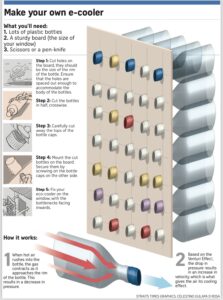
Today we explore a completely passive air conditioner with no moving parts. You may have heard of it. It’s called the Eco-Cooler and it was invented by Ashis Paul, a Bangladeshi innovator.

Screenshot

In 2016, news outlets around the world reported on his creation of a low-cost, electricity-free air conditioner made from recycled plastic bottles. This design aimed to help people in rural Bangladesh cope with the sweltering summer heat, especially those living in homes with limited access to electricity.

The Bernoulli principle and the ideal gas law are the two fundamental principles at play in air conditioners. In theory, an Eco-Cooler functions on the same principles as any compressor driven A/C unit.

The Bernoulli principle states that for an incompressible fluid (like air) flowing in a horizontal stream, an increase in the speed of the fluid is accompanied by a decrease in its pressure. This means as air flows faster, it experiences a drop in pressure. This speed and pressure change is created in the Eco-Cooler as the air stream is forced through the much smaller opening of the bottle neck, causing it to speed up.

The ideal gas law describes the relationship between pressure, volume, and temperature of a gas. According to the ideal gas law, this lower pressure causes the air stream to get hotter by what’s known as adiabatic heating. If this heat can be removed, the air will be chilled upon expansion.

In essence, Bernoulli’s principle creates the pressure differential that drives the heat transfer process in air conditioners, and the ideal gas law explains how this pressure change affects the temperature of the faster moving gas (air in the case of the Eco-Cooler). This interplay of principles is essential for achieving the cooling effect in air conditioners.

I have a treat for you today. I finally took the time to sit down and work out all the engineering behind this simple design.

Here’s what I came up with:

Eco-Cooler, 2L Bottle

Assumptions:
Air speed: v₁ = 2.5 mph (1.12 m/s)
Air pressure: P₁ = 1 atm = 101,325 Pa
Air temp: T₁ = 40°C (313.15°K)
Air density: ρ = 1.225 kg/m³
Specific heat ratio, Cp/Cv: ɣ = 1.4

Given:
D₁ = 4.25” (11 cm)
D₂ = 0.5” (1.27 cm)

Calculate Areas:
A₁ = 𝛑(11/2)² = 95 cm²
A₂ = 𝛑(1.27/2)² = 1.267 cm²

Calculate velocities:
By the continuity formula…
A₁v₁ = A₂v₂
v₁ = 1.12 m/s
v₂ = 95•1.12/1.267 = 84 m/s

Calculate pressures:
ΔP = 0.5 ρ(v₂²-v₁²)
= 0.5•1.225•(84²-1.12²)
= 4,321 Pa
P₁ = 101,325 Pa
P₂ = P₁ + ΔP
P₂ =101,325+4,321 =105,646 Pa
P₂/P₁ = 1.043

Calculate Temperatures:
T₂ = T₁ (P₂/P₁)^((ɣ-1)/ɣ)
= 313.15•(1.043)^(0.4/1.4)
= 316.9°K
= 43.8°C

(As a result of radiative cooling)
T₂ => 313.15°K

After expansion
T₃ = T₂ (P₁/P₂)^((ɣ-1)/ɣ)
= 313.15•(1/1.043)^(0.4/1.4)
= 309.4°K
= 36.3°C
= 97.34°F (down from 104°F)

And there you have it ladies and gentlemen. This is how the Eco-Cooler is supposed to work. However…

The Eco-Cooler, while innovative in its concept of a passive cooling solution, has a mixed reputation. You will find lots of YouTube video reviews online and virtually every one of them claims that it doesn’t work.

I think it’s clear why. In the design, as described, there is literally no means by which to remove the excess heat energy. You must cool the compressed air before allowing it to expand again if you want satisfactory results. Isn’t that how your standard compressor operated A/C unit works? Of course it is.

The faster moving air at the outlet may help increase evaporative cooling effects but that wasn’t the purpose for its compression in this design. It makes absolutely no sense to immediately allow the hot air to re-expand without having removed excess heat energy from it first.

The addition of heat radiating fins to a pipe of increased length would give this thing a fighting chance. The longer path would provide additional time to carry out the heat transfer. In extreme cases it may even be necessary to use a water bath to carry off that excess heat. Yes, this would add expense and complexity but the dividends in performance should be well worth it.

Eco-Cooler Summary

So, to summarize then,

Pros

Low Cost and Simple Design: Made from recycled materials like plastic bottles, the eco-cooler is very inexpensive to build. It doesn’t require electricity, making it suitable for off-grid locations.

Passive Cooling: The design utilizes the Bernoulli principle for a passive cooling effect, offering an alternative to energy-intensive air conditioners.

Environmental Benefits: By using recycled materials and avoiding electricity, the eco-cooler has potential environmental benefits.

Cons

Limited Cooling Capacity: In its basic form, the eco-cooler’s cooling effect is relatively weak and may not be sufficient for significant temperature reduction, especially in hot climates.

Real-World Limitations: Factors like friction and imperfect heat transfer can hinder the effectiveness of the cooling process.

Need for Improvement: The basic design requires modifications like pre-cooling with radiator fins or a water bath to achieve a more noticeable cooling effect.

A Time for Reflection

Let’s consider a new machine with no moving parts… a mirror. Oh. You say you’re not sure a mirror qualifies as a machine?

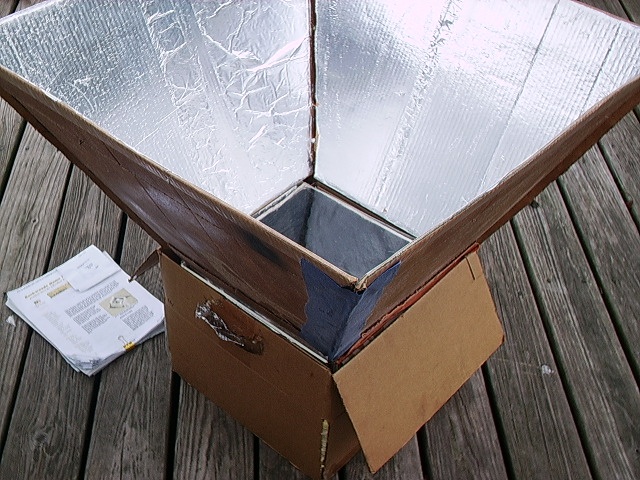
Well, OK then. Let’s make the mirror part of a solar oven. Feel better now? LOL

With that out of the way, let’s say we have a spherical oven with a round opening to receive solar energy. What would it take to create a light collecting mirror that would maximize the amount of energy directed into our oven? Obviously, we need a wide opening at the top. The wider the better, right? And the angle of the mirror should be such that every ray of light that strikes the mirror is reflected into our oven.

Waste not, want not, I always say. Before we leave that thought, can we agree that a rectangular setup of four flat mirrors, although easy to make, cannot meet our requirements since the surfaces near the corners reflect at sub optimal angles.

Break It Down For Me

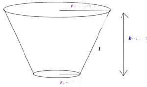
Well, we must conclude that in order to maximize the collection of solar energy fed into a circular opening, we need a conical funnel, technically called a frustum, designed with the following characteristics:

  • Area:

    The area at the top of the funnel must be large enough to capture all the energy required for our design. Solar insolation is generally taken to be 1000 watts per square meter. Good to know.

  • Funnel angle:

    Funnel angle is the angle between the slant side of the funnel and the vertical axis. This is actually called the ‘half-angle’ since there is a duplicate on the other side. It is typically measured in degrees. While it is true that a wider funnel angle will increase the projected area of the funnel’s opening, we already know the area required to accept the amount of sunlight that is to be collected. The angle must be chosen to assure that all the captured light is actually directed into the opening we are trying to target. Although it may look strange, the formula for this angle is:

    Ø = ½cos⁻¹(½(D/d-1))

    Where:
    D is the large diameter at the top and
    d is the smaller bottom diameter

  • Important note: If D/d is 3 or greater, this formula will fail. You must either reduce your large diameter or increase the small one. Ratios of 3 or more require infeasibly small angles. Like, you know? Straight up. That’s no good. LOL. So, watch your selection of D and d values. Oh, and smaller ratios will produce shorter solar funnels. That calculation is the next step.

  • Funnel height:

    The height of the funnel is chosen in coordination with the two diameters to achieve the desired angle. The formula is:

    Height = (D-d)/(2tan Ø)

    Where the variables have been previously defined.

  • Sun angle:

    The funnel should be oriented so that the angle of incidence of sunlight is as close to 90° as possible. This simply means it needs to be pointed directly at the sun if we want to ensure that the maximum amount of sunlight is collected. Surprise! Duh.

Show Me An Example

Ok, for example, we might decide we want to design a 650 watt solar oven. To achieve this would require an area of 0.650 m² at the top of our funnel given the normal amount of solar radiation that reaches us on a sunny day. We can make the following calculation:

D = 2*sqrt(0.650/𝛑) = 0.91 m or 36”

Let’s suppose we decide that a 14” diameter opening is a suitable size to feed our oven. We can now derive the proper funnel angle:

Ø = ½cos⁻¹(½(36/14-1)) = 19.1°

And finally, the height must be:

H = (36-14)/(2*tan(19.1)) = 31.77”

You can check your work by testing this relationship:

(D-d)/(D+d) = tan Ø/tan 2Ø

All that remains is to make a flat pattern to fabricate our funnel. There is a nice calculator available here. It even tells you the size of the sheet material you will need. That material must be as smooth as possible with a mirror finish. Any imperfections will reflect light in directions not consistent with our goal.

Crinkled aluminum foil is probably not the best answer you could come up with. Aluminuzed mylar will probably work for a while. Be aware however, the aluminum will slowly oxidize over time and the alumina (aluminum oxide) will flake off. This is unfortunate indeed.

Explain The Theory Behind Your Numbers

Sure. We are assuming that the solar rays of light are parallel and enter the funnel straight on, that is, we are pointed directly at the sun and perfectly aligned. Any rays coming in without touching the reflector simply enter straight into our oven. In practice, without a functioning tracker device, this won’t be true but we must start somewhere.

We know from physics that the angle of reflection equals the angle of incidence. Our reflector angle must be such that it will map every incoming incident ray across the entire opening. What this means is that a ray that strikes the middle of the reflector must enter the oven through the center of the opening. One that just manages to strike the reflector at the bottom edge must enter right near there while one that catches the top of the reflector must be deflected all the way across the space to enter at the other side. All reflected rays are in parallel as they enter the oven opening.

The angle formula given above does exactly this. In order to achieve this optimal angle, we must adjust the height of our funnel. This is essentially the equivalent of focusing. By adjusting the height we can focus the incoming light to exactly match the size of our opening, thus maximizing the input energy.

So, there you have it. It looks like you got a two-fer with this post. We set out to explore mirrors as machines with no moving parts and learned something about solar ovens in the process. We aim to please. Enjoy.

Bonus2: Another pattern calculator.