The Teachings of a Coffee Percolator

In the first article posted to this website, I acknowledged the coffee percolator as the device that ignited my life long fascination with machines that have no moving parts. I remember being astonished that such a simple contraption should be able to perform the miracle of making 30 cups of coffee seemingly without effort.

Today, I want to spend a little time examining the coffee percolator to see how it works and maybe determine what it is that all machines with no moving parts have in common.

The Percolator: A Simple Brewing Machine

The coffee percolator, a stalwart of kitchens for decades, stands as a testament to the ingenuity of engineering. At its core, it is a machine that achieves its purpose without the need for any moving parts. Yet, it’s a marvel of fluid dynamics and heat transfer.

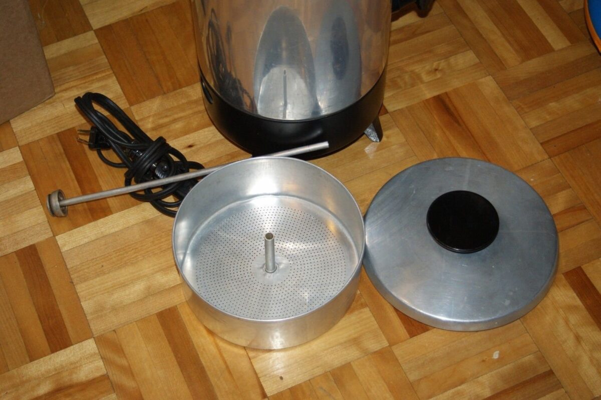
A percolator is essentially a vessel with a central tube that reaches nearly to the bottom. There is a basket containing coffee grounds at the top of the open tube. Water is heated at the base, and as it vaporizes, it forces its way up the tube, lifting the water column as it goes. At the top, the water runs out over the tube and percolates down through the coffee grounds in the basket. It drips back into the main chamber, where it is reheated, and the cycle repeats. The process continues until the desired coffee strength is achieved.

There are three distinct functions involved with the operation of a coffee percolator. None of these require moving parts to be realized.

  1. Water lift:
    To provide liquid to the basket, a bubble pump lifts a column of water through the central tube.
  2. Percolation:
    The water then percolates down through the coffee grounds to extract flavors and color making coffee in the process.
  3. Filtration:
    The coffee is filtered through a porous membrane, usually a disposable paper filter. This helps retain the grounds in the basket while allowing the coffee to slowly return to the reservoir.

The Working Principles

The key to the percolator’s operation lies in the interplay of heat, pressure, and gravity.

There are no pumps, gears, or motors involved; the process is driven solely by the physical properties of water and heat.

The heat source, typically an electric coil or gas flame, provides the energy to convert water into a gas, steam.

Lifting a fluid by gasses is not unique to coffee makers. Here are some other examples:

Geysers:
These natural phenomena occur when groundwater is heated by magma, creating steam that forces water to the surface.

Bubble columns:
These are industrial reactors where gas is bubbled through a liquid, promoting mass transfer and chemical reactions.

Thermosyphons:
A related device that rarely involves a lifting gas, thermosyphons use the natural circulation of a fluid due to density differences caused by temperature variations. They are often used in heating systems and solar water heaters.

While these examples might seem vastly different from a coffee percolator, they all share the underlying principle of fluid movement driven by pressure differentials.

Perks of Percolation

Percolation too is not unique to coffee makers. While the percolator is primarily known for its coffee-making abilities, the principle of percolation itself has far-reaching applications. In chemistry.

Filter washing:
Percolation is a technique used to separate components of a mixture. A solvent is passed through a filter containing the mixture, and different substances are extracted at varying rates. This process is essential in industries such as pharmaceuticals, food processing, and environmental science.

Water purification:
Water filtration systems often employ percolation through layers of sand, gravel, and charcoal to remove impurities. We recently posted an article on this very thing. This natural filtration process is a cornerstone of many municipal water treatment plants.

Cave creation:
Groundwater naturally percolates through rock and soil. This is important for clear, freshwater springs. Over millions of years and under certain conditions, this percolation can create limestone caves. As the water flows, it removes material by dissolving it away.

A Dawning Revelation

The percolator, with its simple yet effective design, showcases the power of fluid dynamics and heat transfer. It is a reminder that complex tasks can often be achieved through elegant and minimalistic means. By understanding the principles behind the percolator, we gain a deeper appreciation for the underlying physics at work in countless other systems, from coffee brewing to water purification and beyond.

Our detailed examination of the coffee percolator has exposed hints to answer our all consuming question:

“What do all machines with no moving parts have in common?”

And the answer is simple … Fluids.

A fluid is a substance that deforms continuously under the application of a shear stress, no matter how small the stress may be.  

In simpler terms, a fluid is a substance that can flow and change its shape easily.

Key characteristics of fluids

  • No definite shape; they take the shape of their container.
  • Ability to flow under the influence of gravity or applied forces.
  • Low resistance to shear stress.

In general, we can talk about two classes of fluids.

Physical fluids:
Fine particulate matter, liquids, gases, and plasmas.

Fluidic Energies:
Electrical currents, electromagnetic waves, sound, fields and thermal gradients.

Fluids are the unseen workhorses of many machines. All machines with no moving parts rely on fluids to do work and perform their function.

Often there are multiple fluids involved. The work is accomplished through changes in pressure, flow, volume, temperature, fields, frequency and other physical phenomena.

Moving forward, every time you encounter a new machine with no moving parts, I would urge you to analyze it to identify the fluid(s) it uses and the fluidic properties employed to make it function.

A Time for Reflection

Let’s consider a new machine with no moving parts… a mirror. Oh. You say you’re not sure a mirror qualifies as a machine?

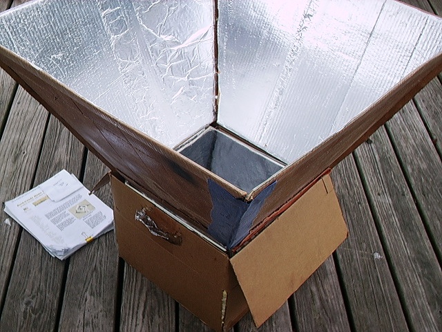
Well, OK then. Let’s make the mirror part of a solar oven. Feel better now? LOL

With that out of the way, let’s say we have a spherical oven with a round opening to receive solar energy. What would it take to create a light collecting mirror that would maximize the amount of energy directed into our oven? Obviously, we need a wide opening at the top. The wider the better, right? And the angle of the mirror should be such that every ray of light that strikes the mirror is reflected into our oven.

Waste not, want not, I always say. Before we leave that thought, can we agree that a rectangular setup of four flat mirrors, although easy to make, cannot meet our requirements since the surfaces near the corners reflect at sub optimal angles.

Break It Down For Me

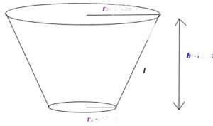
Well, we must conclude that in order to maximize the collection of solar energy fed into a circular opening, we need a conical funnel, technically called a frustum, designed with the following characteristics:

  • Area:

    The area at the top of the funnel must be large enough to capture all the energy required for our design. Solar insolation is generally taken to be 1000 watts per square meter. Good to know.

  • Funnel angle:

    Funnel angle is the angle between the slant side of the funnel and the vertical axis. This is actually called the ‘half-angle’ since there is a duplicate on the other side. It is typically measured in degrees. While it is true that a wider funnel angle will increase the projected area of the funnel’s opening, we already know the area required to accept the amount of sunlight that is to be collected. The angle must be chosen to assure that all the captured light is actually directed into the opening we are trying to target. Although it may look strange, the formula for this angle is:

    Ø = ½cos⁻¹(½(D/d-1))

    Where:
    D is the large diameter at the top and
    d is the smaller bottom diameter

  • Important note: If D/d is 3 or greater, this formula will fail. You must either reduce your large diameter or increase the small one. Ratios of 3 or more require infeasibly small angles. Like, you know? Straight up. That’s no good. LOL. So, watch your selection of D and d values. Oh, and smaller ratios will produce shorter solar funnels. That calculation is the next step.

  • Funnel height:

    The height of the funnel is chosen in coordination with the two diameters to achieve the desired angle. The formula is:

    Height = (D-d)/(2tan Ø)

    Where the variables have been previously defined.

  • Sun angle:

    The funnel should be oriented so that the angle of incidence of sunlight is as close to 90° as possible. This simply means it needs to be pointed directly at the sun if we want to ensure that the maximum amount of sunlight is collected. Surprise! Duh.

Show Me An Example

Ok, for example, we might decide we want to design a 650 watt solar oven. To achieve this would require an area of 0.650 m² at the top of our funnel given the normal amount of solar radiation that reaches us on a sunny day. We can make the following calculation:

D = 2*sqrt(0.650/𝛑) = 0.91 m or 36”

Let’s suppose we decide that a 14” diameter opening is a suitable size to feed our oven. We can now derive the proper funnel angle:

Ø = ½cos⁻¹(½(36/14-1)) = 19.1°

And finally, the height must be:

H = (36-14)/(2*tan(19.1)) = 31.77”

You can check your work by testing this relationship:

(D-d)/(D+d) = tan Ø/tan 2Ø

All that remains is to make a flat pattern to fabricate our funnel. There is a nice calculator available here. It even tells you the size of the sheet material you will need. That material must be as smooth as possible with a mirror finish. Any imperfections will reflect light in directions not consistent with our goal.

Crinkled aluminum foil is probably not the best answer you could come up with. Aluminuzed mylar will probably work for a while. Be aware however, the aluminum will slowly oxidize over time and the alumina (aluminum oxide) will flake off. This is unfortunate indeed.

Explain The Theory Behind Your Numbers

Sure. We are assuming that the solar rays of light are parallel and enter the funnel straight on, that is, we are pointed directly at the sun and perfectly aligned. Any rays coming in without touching the reflector simply enter straight into our oven. In practice, without a functioning tracker device, this won’t be true but we must start somewhere.

We know from physics that the angle of reflection equals the angle of incidence. Our reflector angle must be such that it will map every incoming incident ray across the entire opening. What this means is that a ray that strikes the middle of the reflector must enter the oven through the center of the opening. One that just manages to strike the reflector at the bottom edge must enter right near there while one that catches the top of the reflector must be deflected all the way across the space to enter at the other side. All reflected rays are in parallel as they enter the oven opening.

The angle formula given above does exactly this. In order to achieve this optimal angle, we must adjust the height of our funnel. This is essentially the equivalent of focusing. By adjusting the height we can focus the incoming light to exactly match the size of our opening, thus maximizing the input energy.

So, there you have it. It looks like you got a two-fer with this post. We set out to explore mirrors as machines with no moving parts and learned something about solar ovens in the process. We aim to please. Enjoy.

Bonus2: Another pattern calculator.

Pot-in-Pot Space Heater

In a previous blog post we looked at building a cooling device made with clay flowerpots. Clay is a versatile natural material which has been put to use in hundreds of various ways for thousands of years. Today we will consider the ‘pot-in-pot’ space heater.

Does it work?

Let’s see what kind of performance we can expect from a pot-in-pot space heater. A typical $0.10 tea light burns for 4 hours and has the following dimensions:

1.5” D x 0.65” H = 1.15 cubic inches.

This is equivalent to about 18.85 cubic centimeters (cc).

We know from the tables that paraffin wax has a density of 0.93 g/cc

Therefore, we calculate the mass of paraffin in the candle as:

18.85 cc x 0.93 g/cc = 17.53 g

Heat of combustion for paraffin is 42kJ/g so we determine that the energy produced over a 4 hour time period is:

(17.53g x 42kJ/g)/4h/3600s/h = 51.1 J/s

Yes, 51.1 J/s is a mere 51.1 W. Now, as most published videos on these heaters call for using 4 tea candles at a time, you are looking at a tiny 200 Watt (400 W as configured in the video) space heater with potential carbon monoxide issues… not to mention the hazards of having open flames in your home. Definitely not the kind of thing to have with children and/or pets around the house.

The design shown in the video above appears to be much safer than many of the others you can find online. In an emergency I’m sure it’s worth the risk in order to save a life but, as for a day to day source of warmth?, I wouldn’t recommend it. Even if the fuel cost is less than $5 per day, without adequate ventilation and additional safety precautions this can be a very dangerous device and the actual cost could be tragically higher in the end.